
Last Updated : 2022/10/02
- 2022/10/02: Satellite Tracking with Gpredict
- 2022/09/27: Initial Project Details
Introduction
With the success of my fixed satellite ground station project I always thought that it would be cool to have something more portable, but I wasn’t sure yet wat to use as the actual rotator, especially when it comes to weight and power considerations. I don’t need to be able to go back packing with the setup, but it needs to fit in my car…
When Zane (ZS5ZT) contacted me and offered me a heavy duty pan/title mechanism I jumped at the offer as this could be the solution. Turns out it is a nice little gadget and I’m surprised that not more people have turned these into portable trackers.

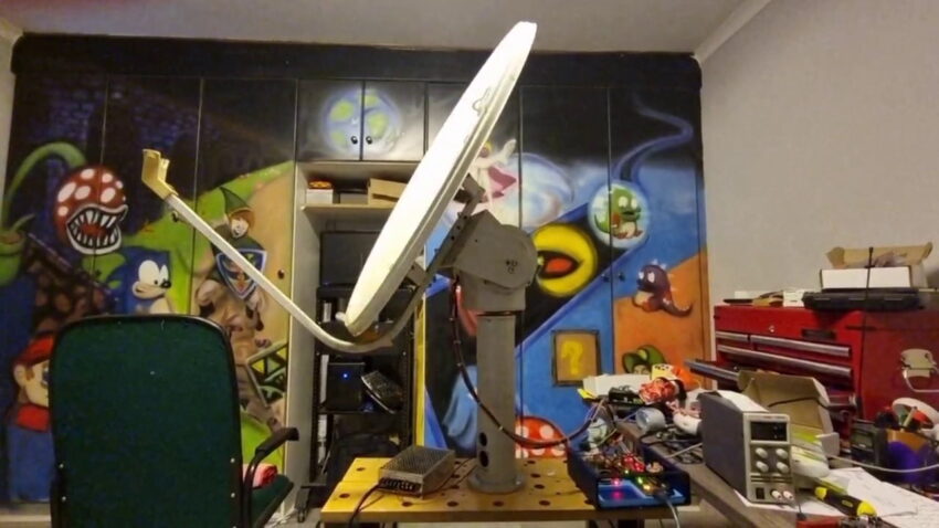
This will most likely turn into a constantly evolving project, especially once I start taking it into the field. Here is a video of it in action. I added a small dish to test it out. The dashboard is running from the pi which I’m accessing via a tablet.
Pan/Tilt Hardware and Modifications
I stripped the pan/title hardware down and discovered that it had the following:
- Two 24V DC Motors
- A multi turn potentiometer (5K) for the elevation
- A 16 core slipring + Vishay Encoder for the azimuth
- Limit switch on the elevation
- Control Electronics
I started by getting rid of the control electronics and testing the motors. They both work perfectly and the gearbox on each turns smoothly without issues. To test I simply put 24v on them to see if they turned.
The slipring and encoder is some nice kit, unfortunately the encoder doesn’t seem to work anymore. I also decided to remove the slipring on this project since I will have antenna cables and such going to to the platform anyways I will be restricting the azimuth to 360 degrees. The slipring can still become handy on another project.
With a few 3d printed bits I added another similar multiturn potentiometer for the azimuth (I’ll take some photos when I open it up again).
The motors and sensors are simple, so I didn’t see the need to reverse engineer the included control board and rather just removed it.
Electronics
For the control box I wanted to do something similar to my fixed ground station, basically a small microcontroller receives azimuth and elevation requests over serial port, it performs the movements based on the request and returns status updates of current azimuth and elevation. The actual smarts comes from a Raspberry PI that will also be built into the control box.
Our complete parts list for the control box consists of the following:
- an Arduino (I’m most likely going to switch this over to a Raspberry Pico at a later stage)
- Dual Bridge DC Motor Controller. The motors use very little current, but I wanted to make sure that I could run at either 12v or 24 v. For these particular motors any L298N motor controller should suffice. For reference I used this one.
- Raspberry PI. I don’t need any crazy processing power so anything that runs Node-Red should be fine.
- A suitable enclosure. I like this Hammond Enclosure (same as used in the Winterhill project)
As mentioned I wanted to keep the firmware on the Arduino as simple as possible. It simply receives an Azimuth/Elevation command and while its moving or on regular interval it will send the current position back over the serial port.
You can find the complete sketch below. Before you can use it you need to specify the pins on which your analog pots are connected, as well as the motor driver connections. The limits are all done in software and is based on the potentiometer readings. This means that you need to calibrate it by specifying a min and max reading from the potentiometer which translates to 0-360 degrees on Azimuth or 0-180 degrees on Elevation. The rest of the code is fairly self explanatory but do contact me if you have specific questions or need me to explain a section.
The received status messages will be in this format:
A:-1/357,E:-1/12The above message means that the current azimuth is 357 and the current elevation is 12. The -1 indicates that its not currently moving, when its moving to specific Az or El it will show the current target instead of -1.
To send a new Az/El command you send the following command:
SET 360 10Where 360 is your requested Azimuth and 10 is your requested Elevation.
Arduino Firmware Sketch
You will need to install the command parser library to compile the sketch.
// tom van den bon - 2022/08/19 - zr6tg

#include <CommandParser.h>

// pins for motor control
int azimutLow = 2;
int azimutHigh = 3;
int elLow = 4;
int elHigh = 5;

// pins for pots
int azPot = A0;
int elPot = A1;

// limits on pots for conversion az/el
int azMin = 600;
int azMax = 706;
int elMin = 250;
int elMax = 690;

// target az/el
int azTarget = -1;
int elTarget = -1;

// command parser for serial comms
typedef CommandParser<> MyCommandParser;
MyCommandParser parser;

void cmd_set(MyCommandParser::Argument *args, char *response) {
  int azCmd = args[0].asInt64;
  int elCmd = args[1].asInt64;

  if (elCmd > 180 or elCmd < 0) return;
  if (azCmd > 360 or azCmd < 0) return;

  azTarget = azCmd;
  elTarget = elCmd;
}

// interval for sending current position if not moving
unsigned long previousMillis = 0;
const long interval = 1000;

void setup() {
  pinMode(azimutLow, OUTPUT);
  pinMode(azimutHigh, OUTPUT);
  pinMode(elLow, OUTPUT);
  pinMode(elHigh, OUTPUT);

  azStop();
  elStop();

  Serial.begin(9600);

  parser.registerCommand("SET", "ii", &cmd_set);
}

void elStop()
{
  digitalWrite(elLow, LOW);
  digitalWrite(elHigh, LOW);
}

void elTurnLow()
{
  digitalWrite(elLow, LOW);
  digitalWrite(elHigh, HIGH);
}

void elTurnHigh()
{
  digitalWrite(elLow, HIGH);
  digitalWrite(elHigh, LOW);
}

void azStop()
{
  digitalWrite(azimutLow, LOW);
  digitalWrite(azimutHigh, LOW);
}

void azTurnLow()
{
  digitalWrite(azimutLow, LOW);
  digitalWrite(azimutHigh, HIGH);
}

void azTurnHigh()
{
  digitalWrite(azimutLow, HIGH);
  digitalWrite(azimutHigh, LOW);
}

void loop() {

  unsigned long currentMillis = millis();

  // parse any commands
  if (Serial.available()) {
    char line[128];
    size_t lineLength = Serial.readBytesUntil('\n', line, 127);
    line[lineLength] = '\0';

    char response[MyCommandParser::MAX_RESPONSE_SIZE];
    parser.processCommand(line, response);
  }

  // sanity check
  if (elTarget > 180) elTarget = -1;
  if (elTarget <0) elTarget = -1;
  if (azTarget > 360) azTarget = -1;
  if (azTarget < 0 ) azTarget = -1;

  // elevation control
  int elReading = analogRead(elPot);
  int elDeg = map(elReading, elMin, elMax, 0, 180);

  if (elDeg < 0) elDeg = 0;
  if (elDeg > 180) elDeg = 180;

  if (elTarget > -1)
  {
    int difference = abs(elTarget - elDeg);

    if (difference > 1 )
    {

      if (elDeg > (elTarget))
      {
        elTurnLow();
      }

      if (elDeg < (elTarget))
      {
        elTurnHigh();
      }
    }
    else
    {
      elStop();
      elTarget = -1;
    }
  }
  else
  {
    elStop();
  }

  // azimuth control
  int azReading = analogRead(A0);
  int azDeg = map(azReading, azMin, azMax, 360, 0);

  if (azDeg < 0) azDeg = 0;
  if (azDeg > 360) azDeg = 360;

  if (azTarget > -1)
  {
    int azDiff = abs(azTarget - azDeg);

    if (azDiff > 3 )
    {

      if (azDeg > (azTarget))
      {
        azTurnLow();
      }

      if (azDeg < (azTarget))
      {
        azTurnHigh();
      }
    }
    else
    {
      azStop();
      azTarget = -1;
    }
  }
  else
  {
    azStop();
  }

  // send status
  if ( azTarget >= 0 || elTarget >= 0 || (currentMillis - previousMillis >= interval) )
  {
    previousMillis = currentMillis;

    Serial.print("A:");
    Serial.print(azTarget);
    Serial.print("/");
    Serial.print(azDeg);
    Serial.print(",");
    Serial.print("E:");
    Serial.print(elTarget);
    Serial.print("/");
    Serial.print(elDeg);
    /*
    Serial.print("-");
    Serial.print(azReading);
    Serial.print(",");
    Serial.print(elReading);
    */
    Serial.println();
  }

}
Control Software

The abovementioned Arduino does the basic control but we are adding a Raspberry PI with Node-Red into the mix to make things smarter. I decided to use Node-Red as it gives me a lot of flexibility to change the system on the fly as needed. It also provides us with a simple dashboard out of the box.
To install Node-Red on your Raspberry Pi the simplest is to use their installation script. You can get all the information here. But essentially you just need to run the following 1 liner to have Node-Red installed:
bash <(curl -sL https://raw.githubusercontent.com/node-red/linux-installers/master/deb/update-nodejs-and-nodered)Once installed you can run the following command to start Node-Red:
node-redIf you prefer to have Node-Red auto start on bootup then you can enable the service with the following command:
sudo systemctl enable nodered.serviceYou can access the web-based editor at http://<ip of your raspberry pi>:1880. On my side I have setup the following flow

This is a very simple version where it connects to the arduino via a usb port. Whenever it reads the current Az/El it will show it on a gauge graph. I have added 2 sliders that allows you to specify an Az/El value which gets sent to the Arduino when you press a button. As an example I’ve also added two preset buttons to move to a fixed position.
This is a very basic flow to get you started, but can be expanded by connecting it to satellite prediction software, or maybe an aprs server to point to an aprs tracker, etc. I will expand this document with more advanced flows, but this should be enough to test your setup.
You can import this flow into your setup using the following code snippet:
[{"id":"42f128ee4e0cd227","type":"tab","label":"Portable Az/EL Basic","disabled":false,"info":"","env":[]},{"id":"f3a335573256917d","type":"serial in","z":"42f128ee4e0cd227","name":"RotatorSERIAL","serial":"7eb28cc5dfde1973","x":140,"y":80,"wires":[["8ea4dedfdca1094b"]]},{"id":"3093290d7d4ef949","type":"ui_button","z":"42f128ee4e0cd227","name":"","group":"99b6416cabfcc5c0","order":1,"width":0,"height":0,"passthru":false,"label":"Home","tooltip":"","color":"","bgcolor":"","className":"","icon":"","payload":"SET 360 10","payloadType":"str","topic":"topic","topicType":"msg","x":130,"y":200,"wires":[["600ad39ff69fcc3e"]]},{"id":"600ad39ff69fcc3e","type":"serial out","z":"42f128ee4e0cd227","name":"","serial":"7eb28cc5dfde1973","x":440,"y":200,"wires":[]},{"id":"cad1cf5705707f4f","type":"ui_slider","z":"42f128ee4e0cd227","name":"","label":"EL","tooltip":"","group":"8e3588f465437093","order":1,"width":"4","height":"1","passthru":true,"outs":"all","topic":"topic","topicType":"msg","min":"0","max":"90","step":1,"className":"","x":650,"y":160,"wires":[["96ad914b32db0601","9cd016e60d52104b"]]},{"id":"8ef870a4f6782157","type":"ui_slider","z":"42f128ee4e0cd227","name":"","label":"AZ","tooltip":"","group":"8e3588f465437093","order":3,"width":"4","height":"1","passthru":true,"outs":"all","topic":"topic","topicType":"msg","min":"1","max":"360","step":1,"className":"","x":650,"y":220,"wires":[["9843161cac13f873","d79850bde6b3868c"]]},{"id":"96ad914b32db0601","type":"function","z":"42f128ee4e0cd227","name":"Save Elevation Value","func":"flow.set(\"set_el\", msg.payload)\nreturn null;\n","outputs":1,"noerr":0,"initialize":"","finalize":"","libs":[],"x":920,"y":160,"wires":[[]]},{"id":"9843161cac13f873","type":"function","z":"42f128ee4e0cd227","name":"Save Azimuth Value","func":"flow.set(\"set_az\", msg.payload)\nreturn null;\n","outputs":1,"noerr":0,"initialize":"","finalize":"","libs":[],"x":920,"y":220,"wires":[[]]},{"id":"8ea4dedfdca1094b","type":"function","z":"42f128ee4e0cd227","name":"Read Az/El","func":"\nvar data = msg.payload.split(',');\nvar elevRaw = data[1].split('/')[1].replace('\\n', '');\nvar aziRaw = data[0].split('/')[1].replace('\\n', '');\n\n\nvar azimuth = parseInt(aziRaw);\nvar elevation = parseInt(elevRaw);\n\nvar newMsg = { payload : { 'azimuth' : azimuth, 'elevation' : elevation }}\nreturn newMsg;","outputs":1,"noerr":0,"initialize":"","finalize":"","libs":[],"x":330,"y":80,"wires":[["eea8120101151f4a","cfef0ef950c0ed06"]]},{"id":"eea8120101151f4a","type":"ui_gauge","z":"42f128ee4e0cd227","name":"","group":"1ba28321f4bf2f1b","order":3,"width":0,"height":0,"gtype":"gage","title":"Elevation","label":"Degrees","format":"{{msg.payload.elevation}}","min":0,"max":"180","colors":["#00b500","#00b400","#00b400"],"seg1":"","seg2":"","className":"","x":520,"y":60,"wires":[]},{"id":"cfef0ef950c0ed06","type":"ui_gauge","z":"42f128ee4e0cd227","name":"","group":"1ba28321f4bf2f1b","order":3,"width":0,"height":0,"gtype":"gage","title":"Azimuth","label":"Degrees","format":"{{msg.payload.azimuth}}","min":0,"max":"360","colors":["#00b500","#00b400","#00b400"],"seg1":"","seg2":"","className":"","x":520,"y":100,"wires":[]},{"id":"9cd016e60d52104b","type":"ui_text","z":"42f128ee4e0cd227","group":"8e3588f465437093","order":2,"width":"2","height":"1","name":"","label":"","format":"{{msg.payload}}","layout":"row-spread","className":"","x":890,"y":80,"wires":[]},{"id":"d79850bde6b3868c","type":"ui_text","z":"42f128ee4e0cd227","group":"8e3588f465437093","order":4,"width":"2","height":"1","name":"","label":"","format":"{{msg.payload}}","layout":"row-spread","className":"","x":870,"y":300,"wires":[]},{"id":"70276d939b1775a4","type":"ui_button","z":"42f128ee4e0cd227","name":"","group":"8e3588f465437093","order":4,"width":0,"height":0,"passthru":false,"label":"Goto AZ/EL","tooltip":"","color":"","bgcolor":"","className":"","icon":"","payload":"","payloadType":"str","topic":"topic","topicType":"msg","x":150,"y":280,"wires":[["663cd8e92775b6f7"]]},{"id":"663cd8e92775b6f7","type":"function","z":"42f128ee4e0cd227","name":"Get Az/El","func":"var newAzimuth = flow.get('set_az')\nvar newElevation = flow.get('set_el')\nmsg.payload = 'SET ' + newAzimuth + \" \" + newElevation;\nreturn msg;\n\n","outputs":1,"noerr":0,"initialize":"","finalize":"","libs":[],"x":340,"y":280,"wires":[["600ad39ff69fcc3e"]]},{"id":"5a12fcdcc8de3928","type":"ui_button","z":"42f128ee4e0cd227","name":"","group":"99b6416cabfcc5c0","order":1,"width":0,"height":0,"passthru":false,"label":"Up","tooltip":"","color":"","bgcolor":"","className":"","icon":"","payload":"SET 360 90","payloadType":"str","topic":"topic","topicType":"msg","x":130,"y":240,"wires":[["600ad39ff69fcc3e"]]},{"id":"7eb28cc5dfde1973","type":"serial-port","serialport":"/dev/ttyACM0","serialbaud":"9600","databits":"8","parity":"none","stopbits":"1","waitfor":"","dtr":"none","rts":"none","cts":"none","dsr":"none","newline":"\\n","bin":"false","out":"char","addchar":"\\n","responsetimeout":"10000"},{"id":"99b6416cabfcc5c0","type":"ui_group","name":"Presets","tab":"d0791bf31955f540","order":1,"disp":true,"width":"6","collapse":false,"className":""},{"id":"8e3588f465437093","type":"ui_group","name":"Rotator Control","tab":"d0791bf31955f540","order":3,"disp":true,"width":"6","collapse":false,"className":""},{"id":"1ba28321f4bf2f1b","type":"ui_group","name":"Rotator","tab":"d0791bf31955f540","order":2,"disp":true,"width":"6","collapse":false,"className":""},{"id":"d0791bf31955f540","type":"ui_tab","name":"Az/El Rotator","icon":"dashboard","disabled":false,"hidden":false}]This should get you going with the initial setup. Let me know if any of the above needs more detail/explanation 🙂
I have lots of experiments that I want to do with this setup, so this page will get expanded over time with more information.
Satellite Tracking
Its all good and well we can send manual Azimuth and Elevation commands to set the position. But what we actually want is to automate the tracking by connecting it to a Satellite Tracking Application. Here is a post about emulating Hamlib in Node-Red to connect it to Gpredict.
Adding Satellite Tracking to Portable Rotator
Next Steps/Todo List
- Example Flow for APRS Tracking
Example Flow for Satellite Prediction Connection- Vehicle installation (Roof Rack Kit)
- Take it out to the field for QO-100 operation
- Take it out to the field for Leo Satellites operation
hello Tom,
Did you received my previous mail?
73 de ON4RDB
Roland